Angled Studio
- Location
- Concept study
- Type
- Residential
- Year
- 2026
A furnished lighting concept explored through angled Blender renders and matching calculated amber heatmaps. Revised layouts include enclosed service rooms, practical circulation and carefully oriented furniture.
- Scope
- Lower level; Upper level
- Systems
- Nuordic N55 10 W / 3000 K / 50 degree measured IES for interior downlights. Generic 1000 lm / 60 degree outdoor downlights where shown.
- Targets
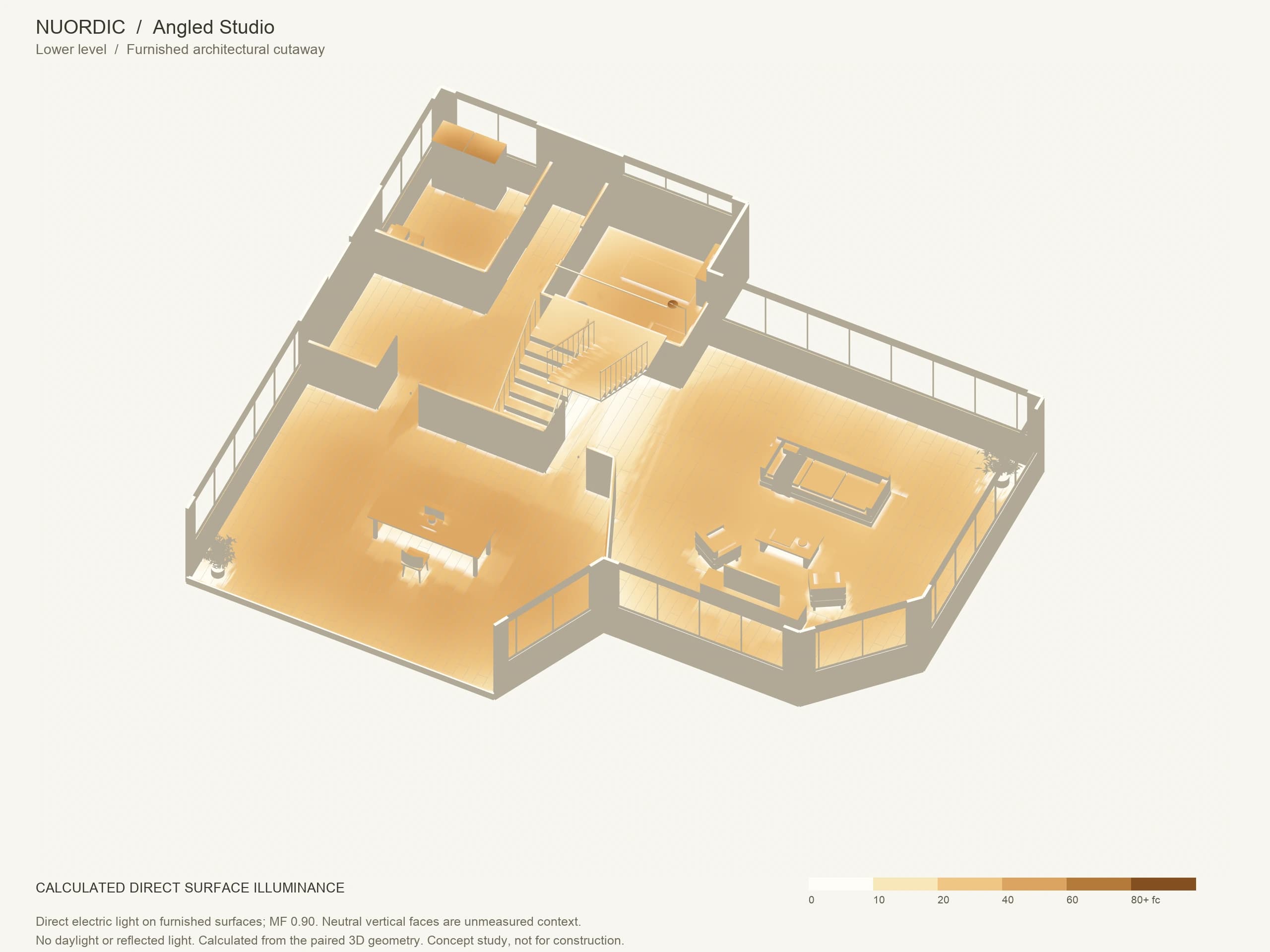
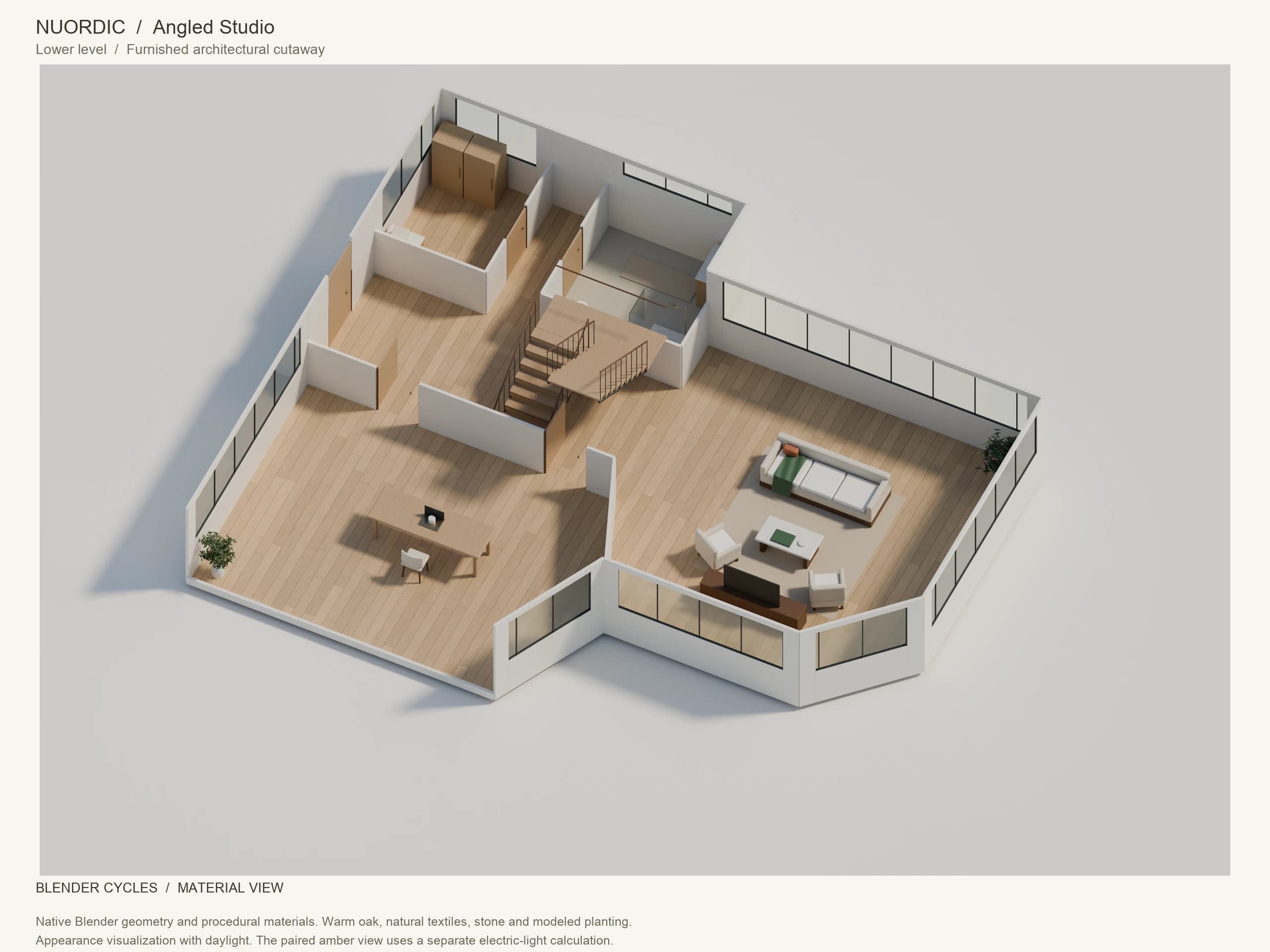
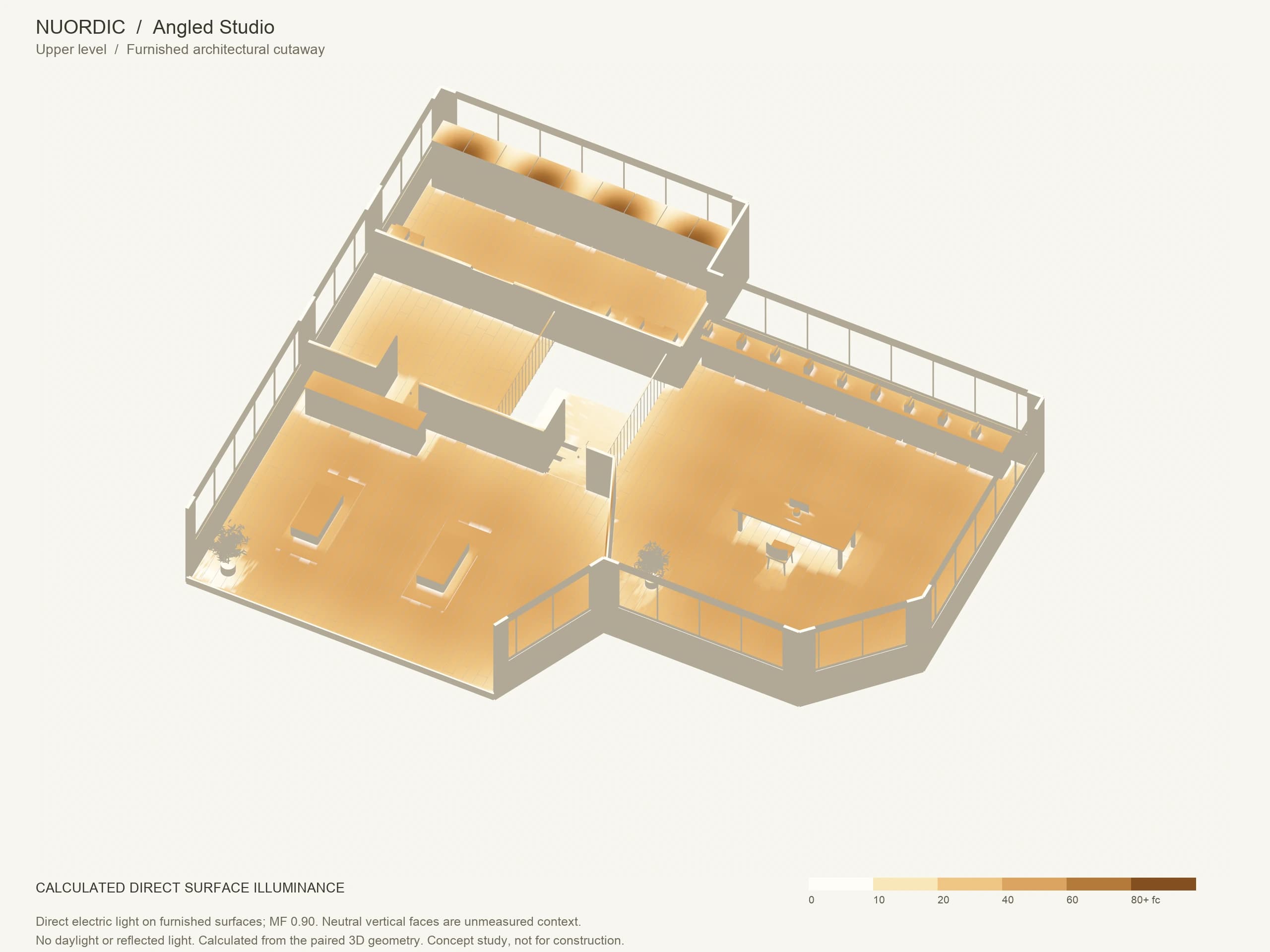
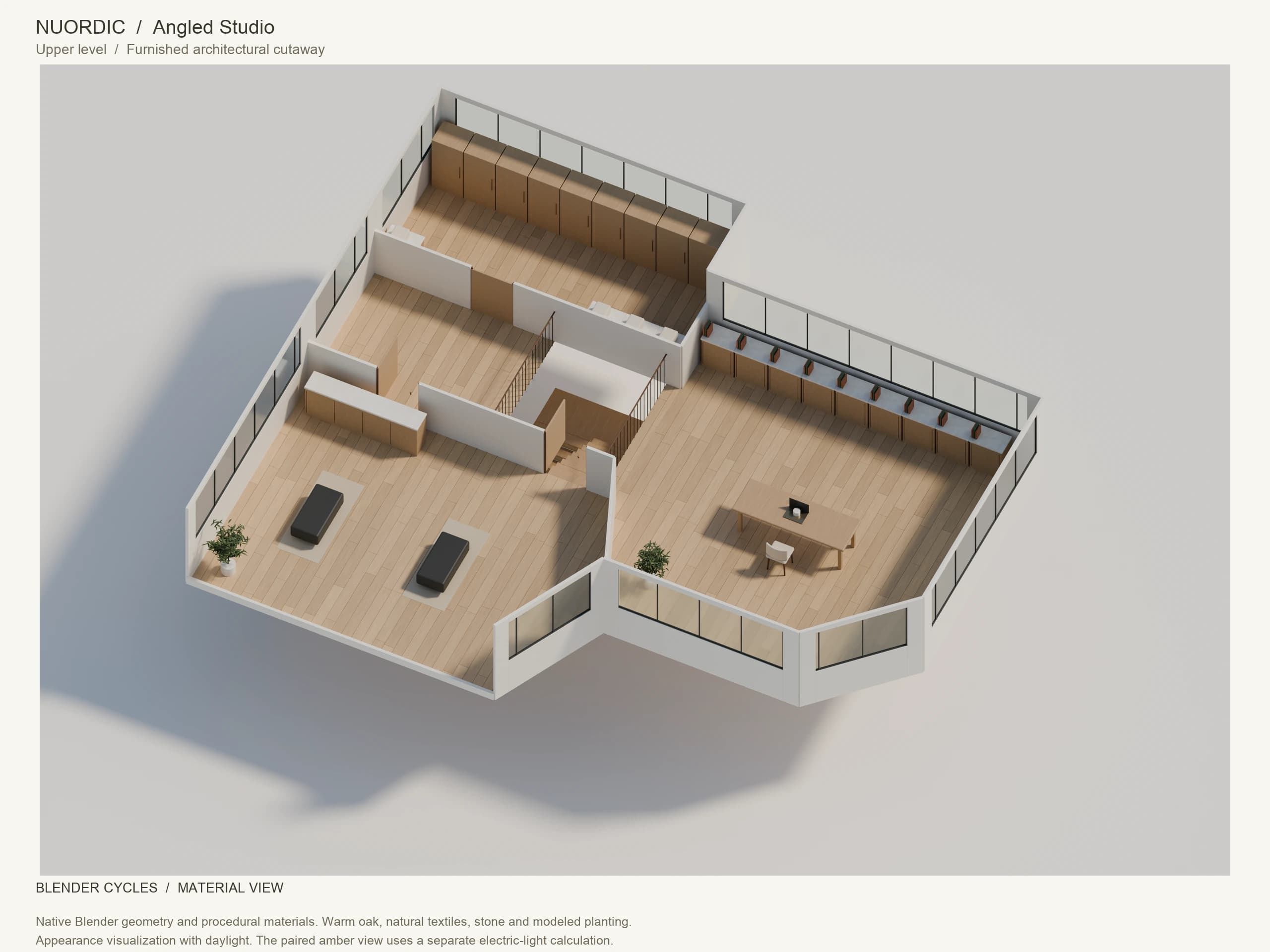
- Concept studies, not for construction. Flat tables: empty 2.5 ft horizontal workplane, 0.25 ft grid, MF 0.90; opaque walls and closed privacy doors. Upper stair voids excluded; lower stair-void lights at 19 ft. Furnished amber views: direct electric light on upward-facing surfaces with modeled furniture shadows; neutral vertical faces are unmeasured. Both calculations exclude daylight, reflections and interlevel transfer. Appearance renders use daylight. Walls are sectioned for visibility.
Furnished in 3D
The space, and the light within it.
Explore each furnished floor from above. Drag the handle to compare the material view with its amber illuminance heatmap, including furniture shadows. Material views are appearance visualizations.
Calculated results
Every room against its target.
Calculated on the empty workplane specified in each row. Furnished 3D heatmaps show light on visible surfaces, so their values can differ from these workplane results.
| Room | Plane | Target fc | Average fc | Minimum fc | Uniformity |
|---|---|---|---|---|---|
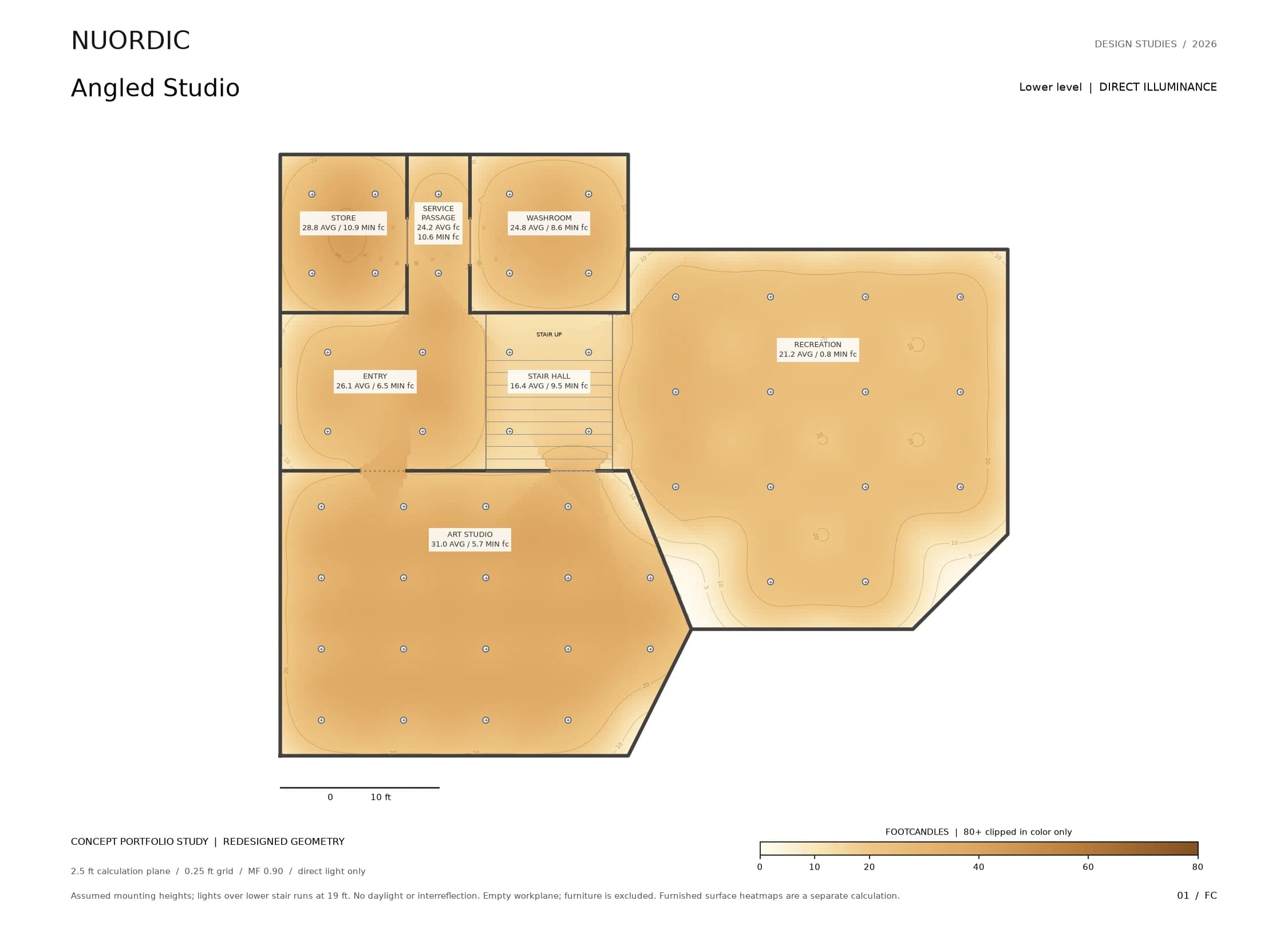
| Lower level: Art studio | Horizontal plane, 2.5 ft above floor; direct component | 30 | 31 | 5.7 | 0.185 |
| Lower level: Entry | Horizontal plane, 2.5 ft above floor; direct component | 5 | 26.1 | 6.5 | 0.249 |
| Lower level: Stair hall | Horizontal plane, 2.5 ft above floor; direct component | 5 | 16.4 | 9.5 | 0.577 |
| Lower level: Recreation | Horizontal plane, 2.5 ft above floor; direct component | 10 | 21.2 | 0.8 | 0.036 |
| Lower level: Store | Horizontal plane, 2.5 ft above floor; direct component | 10 | 28.8 | 10.9 | 0.379 |
| Lower level: Washroom | Horizontal plane, 2.5 ft above floor; direct component | 10 | 24.8 | 8.6 | 0.347 |
| Lower level: Service passage | Horizontal plane, 2.5 ft above floor; direct component | 5 | 24.2 | 10.6 | 0.44 |
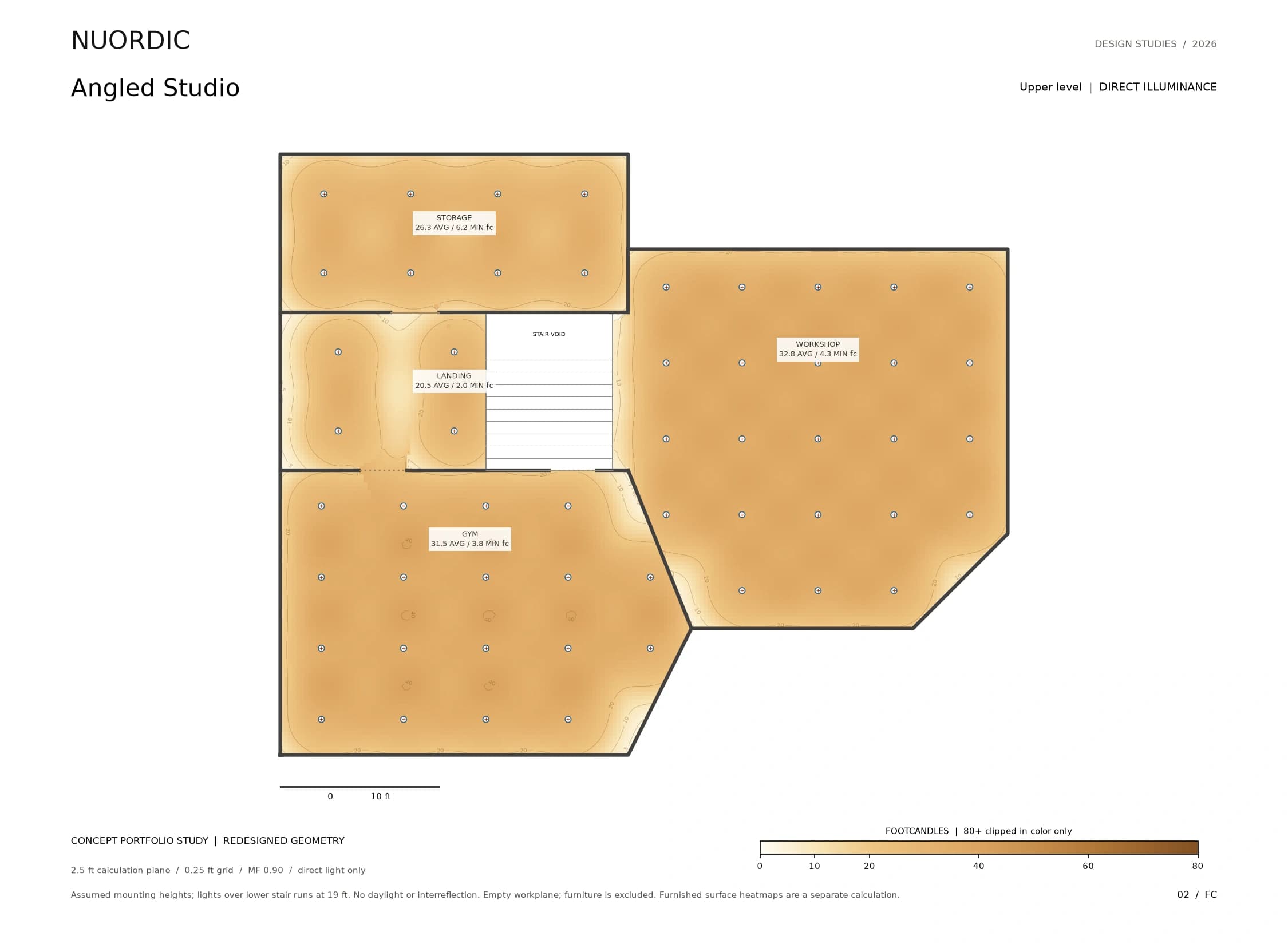
| Upper level: Gym | Horizontal plane, 2.5 ft above floor; direct component | 20 | 31.5 | 3.8 | 0.122 |
In the package
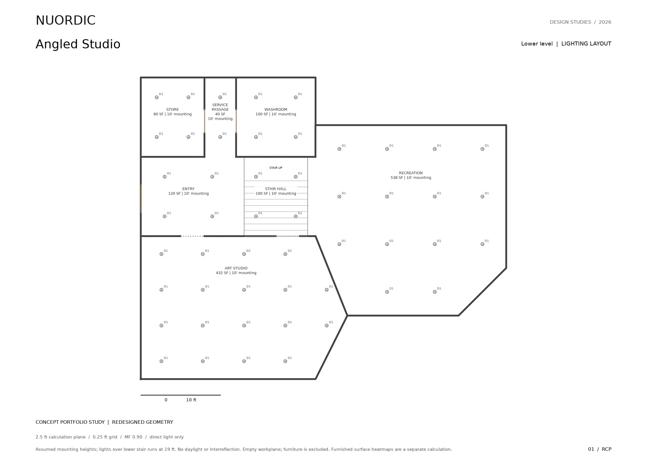
- Lower level lighting layoutRCP-01
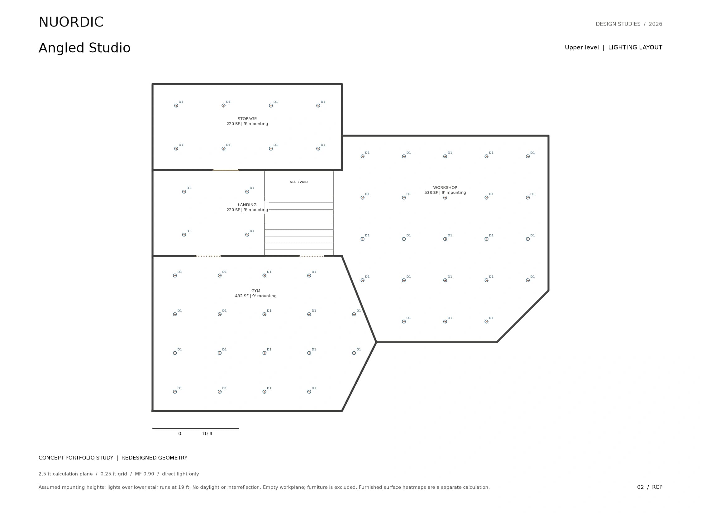
- Upper level lighting layoutRCP-02
- Lower level direct illuminanceFC-01
- Upper level direct illuminanceFC-02
- Calculation results and assumptionsCALC
Supporting drawings
Flat plans and heatmaps.
Next package
Folded Roof House
Concept study · Residential
Your project
Send a floor plan. Get a lighting plan back.